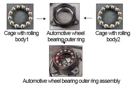
The third generation of automotive wheel bearings has made significant progress in design and development, with several functional components concentrated on the bearing and the flange connecting the steering knuckle (or suspension) integrated into the outer ring. The high level of integration reduces mass and form factor and improves reliability, but likewise increases the difficulty of assembling the bearing itself. Bearing The outer ring of the bearing and the assembly of the cage with a good rolling body are shown in Figure 1. Because of the complex structure of the shape, most of the domestic automotive bearing factory assembly steps The assembly step is still carried out manually. The efficiency of traditional manual assembly is low, labor intensity and easy to affect the cleanliness and precision of the bearing so that the assembly quality is not The quality of the assembly is not stable. In response to this problem, we have designed and developed an automatic assembly machine that can be applied to several models of automotive wheel bearings. The device can efficiently complete the assembly of the outer ring of the wheel bearing and the bearing The device can efficiently complete the assembly of the outer ring of the automotive wheel hub bearing and the cage with rolling elements.
1 Design and optimization of the mechanical structure of the assembly device
1) Overall structural solution of the device
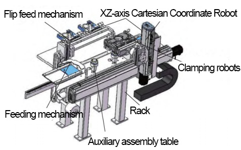
The overall mechanical structure of the automotive wheel hub bearing outer ring assembly automatic assembly device is shown in Figure 2. It consists of six parts, including a flip feed mechanism, feeding mechanism, auxiliary assembly table, clamping robot, xz-axis right-angle coordinate robot, and frame. The flip feeder will send the cage with the rolling body to the auxiliary assembly table; the right-angle coordinate robot drives the clamping robot to pick up the outer ring of the bearing, then move horizontally to the top of the first assembly station, and then move down vertically to load the first cage with the rolling body; the outer ring of the bearing flips 180° and moves horizontally to the top of the second assembly station, then move down vertically to load the second cage with the rolling body. The bearing outer ring assembly will be sent to the designated position after the assembly is completed, and then the feeding mechanism will use the cylinder to drive the stopper to send the completed bearing outer ring assembly to the next station.
2) Main mechanism design
A. xz-axis Cartesian Coordinate Robot
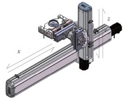
The assembly process is mainly based on linear motion, and each axis of motion usually corresponds to the x-axis, y-axis, and z-axis in the Cartesian coordinate system, generally the x-axis and y-axis are horizontal axes of motion, and the z-axis is the up and down axis of motion. The robot was selected as a two-dimensional xz-axis Cartesian coordinate robot to meet the requirements of the assembly task and the space constraints of the site. The construction method is cantilevered, as shown in Figure 3. Both axes of linear motion are The ball screw linear module is used for both axes, driven by a separate servo motor, and the single-axis repositioning accuracy is ±0.01. The single-axis repositioning accuracy is ±0.01 mm, and the linear motion speed is as fast as 3 000 mm/s.
B. Clamping manipulator
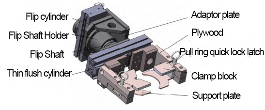
The structure of the clamping manipulator is shown in Fig. 4, including two parts: the clamping member and the turning member. The clamping member consists of a thin flush cylinder, a clamping plate, a pull ring quick-lock pin, a clamping block, and a support plate. The clamping block and the support plate are fixed to the clamping plate by using the pull ring quick-lock pins, which can be easily replaced and maintained. The thin flush cylinder transfers the clamping force to the clamping plate, and the two clamping blocks are driven by the clamping plate to complete the clamping of the outer ring of the wheel bearing. There is a pair of crescent-shaped support plates under the clamping plate, whose inner diameter is equal to the outer diameter of the clamping part, and the support plates can effectively assist in clamping the outer ring of the wheel bearing and prevent it from falling off at the same time.
The overturning member mainly consists of the overturning cylinder, overturning shaft seat, overturning shaft, and adapter plate. When the clamping member is driven by the overturning cylinder, the bending moment that the overturning cylinder can withstand is limited, so if the clamping member is directly connected to the overturning cylinder, the bending moment generated by the self-weight of the clamping member will be applied to the overturning cylinder, which will shorten the service life if the overturning cylinder is subjected to the bending moment for a long time. To avoid the bending moment of the flipping cylinder, the flipping cylinder is replaced by the flipping shaft holder. In Fig. 4, the flip cylinder transmits the rotational motion to the flip shaft, and the flip shaft is connected with the clamping member through the flange to transmit the rotational motion to the clamping member; the bending moment generated by the clamping member will be borne by the flip shaft holder, and then the whole clamping manipulator is fixed to the z-axis moving screw using the adapter plate.
C. Auxiliary assembly table
To make the outer ring of the automotive wheel bearing hold the cage better, an annular positioning tab is designed on the outer ring of the bearing. This tab can hold the cage position without using other parts so that the cage cannot move freely. However, the maximum diameter of the cage with rolling elements is larger than the inner diameter of the ring locating boss. The maximum diameter of the cage with a rolling body is larger than the inner diameter of the ring locating tab, so the cage needs to be deformed and shrunk during the assembly process. Therefore, the cage needs to be deformed and contracted during the loading process to complete the assembly successfully. Accordingly, the auxiliary assembly table is designed as shown in Figure 5. This assembly table allows the cage to be deformed enough to complete the assembly after being slightly squeezed. This assembly table allows the cage to be deformed enough to complete the assembly after being slightly squeezed.
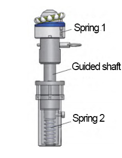
The feed tilting mechanism delivers the cage with the rolling body to the auxiliary assembly table and the assembly and extrusion process can be divided into the following two steps. In the first step, the initial state of the cage with a rolling body is lifted by spring 1 and placed at an angle; the clamping robot holds the outer ring of the wheel bearing and moves it down along the z-axis; the end of the cage with the rolling body supported by spring 1 is loaded into the outer ring of the wheel bearing first. This process can be completed smoothly without squeezing force because the cage with the rolling body is tilted and the ball itself is very smooth and can adjust its position automatically; in the second step, after the cage with the rolling body is installed, the clamping manipulator continues to move downward, which will overcome the spring force of spring 1 and make the cage with a rolling body move from tilt to horizontal, while the guide At the same time, the guide shaft moves downward to squeeze spring 2, and the upward squeezing force provided by spring 2 will gradually increase so that the cage will be deformed enough to finish the assembly.
3) Key organization optimization
A. Defects of the flip feed mechanism
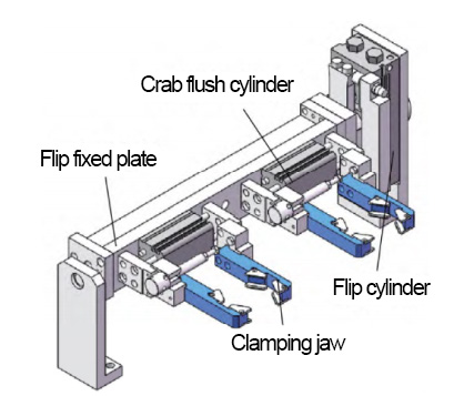
The feeding task of the cage with a rolling body is realized by two pairs of jaws driven by the flip cylinder and two crab cylinders. After the jaws hold the cage with the rolling body, the jaws are rotated 180° by the flip cylinder to reach the upper part of the auxiliary assembly table; after releasing the jaws, the cage with the rolling body drops to the auxiliary assembly table. After releasing the jaws, the cage with a rolling body drops down to the auxiliary assembly table, and then the feeding mechanism is reset after finishing feeding, waiting for the After finishing feeding, the flip feeder mechanism is reset and waiting for the next round of feeding. The structure of the flip feeder mechanism is shown in Figure 6.
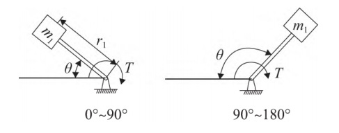
The eccentric mass of the flip mechanism is large, and during the flip process from 0° to 90°, the eccentric mass does negative work to hinder the flip motion; during the flip process from 90° to 180°, the eccentric mass does positive work to accelerate the flip. The motion sketch of the overturning feeding mechanism is shown in Figure 7. In order to simplify the analysis process, ignore the frictional moment of the rotating shaft, according to the law of rotating rigid body, we can get the moment balance equation in 0°~90° and 90°~180° turning respectively:
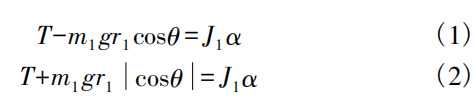
Where: J1 is the rotational inertia of the turning jaw; α is the angular acceleration of the center of mass; T is the output torque of the turning cylinder; m1 is the eccentric mass; r1 is the eccentric distance; θ is the turning angle. Due to the influence of the eccentric mass of the flipping mechanism, the flipping starts slowly from 0° to 90° and accelerates from 90° to 180°, so the overall movement of the flipping feeding mechanism is not smooth; at the same time, the angular velocity at the end of the movement stroke is too large, which will produce a large impact, and the frequent impact will reduce the service life of the mechanism. Based on the above two shortcomings, the existing mechanism is optimized.
B. Mechanism optimization scheme
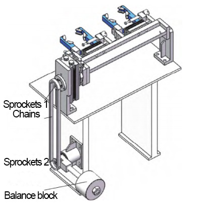
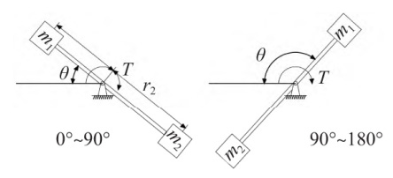
Based on the existing layout of the tilting feeding mechanism, the optimization is to add a balancing device to balance the eccentric mass of the existing mechanism. As shown in Figure 8, the tilting shaft is connected to the sprocket through the keyway, and the sprocket drives the chain to transfer the tilting motion to the balancing device. The sprocket drives the chain to transfer the tilting motion to the balancing block. When moving from 0° to 180°, the eccentric mass of the tilting jaws does negative work first and then positive work. The balanced block will do positive work first and then negative work, which is exactly the same as the eccentric mass of the tilting mechanical jaw. The eccentric mass of the mechanical claw will balance each other, and the sketch of the mechanical movement is shown in Fig. 9. Now Set the balance block mass is greater than the eccentric mass of the flip mechanical jaw, its role in The effect is that the extra mass of the balancing block can increase the tilting acceleration when the tilting motion starts. When the tilting motion starts, the extra mass of the balance block can increase the tilting acceleration; when the motion reaches the end, the tilting acceleration is reduced. The mass of the balancing block has an upper When the tilting mechanism moves to 180°, the torque generated by the mass of the balance block is smaller than that of the tilting cylinder and the tilting mechanism. When the tilting mechanism moves to 180°, the torque generated by the mass of the balance block is smaller than the torque generated by the eccentric mass of the tilting cylinder and the tilting jaws. The expression is
Where: m2 is the eccentric mass of the balancing block; r2 is the eccentric distance of the balancing block. According to the existing r2 = 2r1, the mass of balancing block m2 can be obtained according to the layout of equipment in the field.
C. Dynamical analysis to verify the feasibility
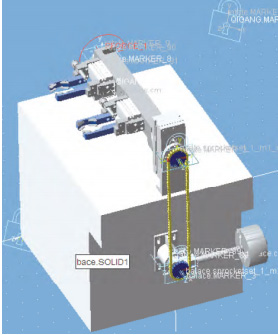
Adams software has a powerful dynamics solver, but the solid modeling function is weak. In this paper, the 3D modeling software Solidworks is used to simplify the flipping mechanism and import the mechanism model into Adams by using the interface between Solidworks and Adams software. Once the geometric model is established, the kinematic sub and kinematic constraints can be applied to the model. The Revolute sub-constraints are applied to the corresponding rotating joints; the Fixed sub-constraints are used to fix the base and the ground. For the flip mechanism to move from 0° to 180°, it is necessary to establish the angle measurement for the rotating joints, and to establish the sensor for the angle measurement, so that the motion will be terminated when the angle exceeds 180°. The simulation analysis model is shown in Figure 10.
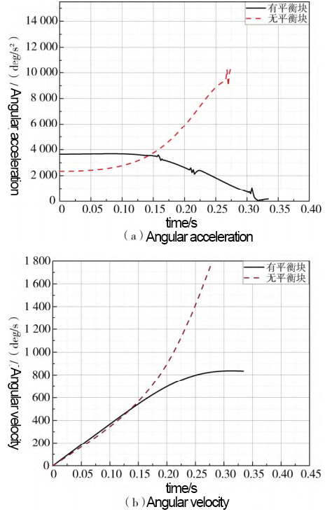
Adams was used to simulating the overturning mechanism without and with the balance block respectively. The angular acceleration and angular velocity at the center of mass of the flipping mechanism are simulated by Adams. The intermittent curves of angular acceleration and angular velocity at the center of mass of the tilting mechanism are shown in Fig. 11. From Fig. 11(a), we can see that the angular acceleration and angular velocity at the center of mass of the overturning mechanism vary from time to time compared with the angular acceleration and angular velocity at the center of mass of the flipping mechanism are shown in Fig. 11. The angular acceleration of the tilting mechanism with counterbalance is large at the beginning of the motion, and then decreases gradually as the tilting motion proceeds and reaches the end of the stroke. From Fig. 11(b), it can be seen that the velocity of the tilting mechanism with a counterbalance is smaller than that of the tilting mechanism without a counterbalance. The speed of the tilting mechanism with a counterbalance is smaller than that of the tilting mechanism without a counterbalance. The speed change of the overturning process of the mechanism with counterbalance is relatively flat. According to the momentum theorem, the smaller the speed to the end, the smaller the impact force generated. Therefore, the simulation verifies that the optimization of the mechanism meets the expected goal.
2 Control System
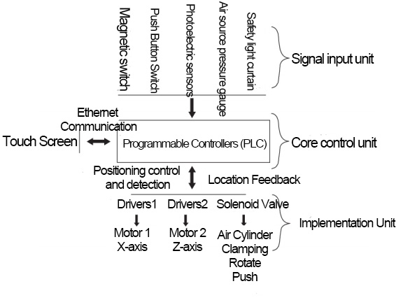
The control system structure of the automotive wheel bearing outer ring assembly device is shown in Fig. 12, which mainly includes a signal input unit, core control unit, actuator unit, and human-machine interaction touch screen.
The magnetic switch in the signal input unit is used to judge the position of the cylinder and limit the x-axis and z-axis of the right-angle coordinate robot; the button switch is used to control the start and stop of the circuit; the photoelectric sensor is used to judge whether the cage with rolling body and the outer ring of the wheel bearing is in the desired position; the air source pressure gauge is used to monitor whether the overall air pressure of the mechanism meets the preset demand; the safety light curtain is used to prevent the operator's body parts from accidentally touching the inside of the device. The safety light curtain is used to prevent the operator's body parts from accidentally touching the inside of the equipment. The core control unit is a programmable logic controller (PLC), which is compact and easy to communicate and controls the actuators through digital or analog inputs and outputs. The PLC outputs pulses to control the operation of the motor through positioning commands, while the encoder on the servo motor feeds real-time position signals to the PLC to achieve closed-loop control and ensure accurate displacement in the x-axis and z-axis; the solenoid valve receives electrical signals from the PLC to control the cylinder for the corresponding action. The main function of the touch screen is to display the running status, position coordinates, position of each mechanism, and the number of completed assemblies of the right-angle coordinate robot in real-time when the system is running, and the touch screen will remind the corresponding error code when there is an error in the system.
3 Application operation test
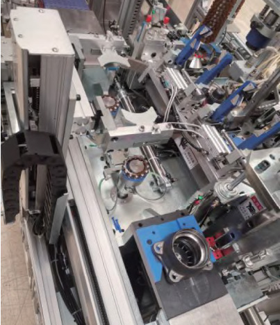
The device was applied to the actual production line of the company, as shown in Figure 13. The assembly of the outer ring and the cage with the rolling element is tested in 200 groups. The test results: The assembly machine can complete one assembly every 13 s, which meets the enterprise's requirement of 15 s. The success rate of assembly is 100%, and the productivity is increased by 44% compared with manual work. The accuracy, efficiency, and stability of the assembly device can meet the actual production requirements of the company.
4 Conclusion
A fully automatic assembly device was designed by studying the outer ring assembly of an automotive wheel hub bearing. The device uses an AC servo motor as the main drive to achieve accurate position control; the clamping robot can accurately and stably hold the workpiece; the auxiliary assembly table makes the cage deformation enough to help the device complete the assembly smoothly with very small squeezing force; the optimized flip feed mechanism is simulated and analyzed by Adams, and it is proved that the optimized mechanism meets the expected target. The assembly device has been successfully put into production, and the successful application of the device has enabled the company to reduce labor costs, improve work efficiency and assembly quality, and also provide a reference for other companies in the automotive field to upgrade their production methods.
References:
[1] Design of picking robots on the production line - taking cans as an example [J]. He Q, Chen H, Yu W, Chen Y. Machine manufacturing and automation. 2019(05)
[2]Definition, classification, and technical development trend of wheel bearings[J]. Song Xiangfeng. Automotive practical technology. 2018(12)
[3]Analysis and simulation of six-degree-of-freedom industrial robot dynamics[J]. Li Qingling, Zhao Yongsheng. Journal of Shanghai Institute of Electrical Engineering. 2008(04)
[4] A brief description of Cartesian Coordinate Robot and its application[J]. Li G, Zhou W. Bao. Servo control. 2008(09)
[5] A Brief Introduction to Cartesian Coordinate Robots and Their Applications [J]. Li G, Zhou W. Bao. Servo Control. 2008 (09)

 All uploads are secure and confidential